Introduction
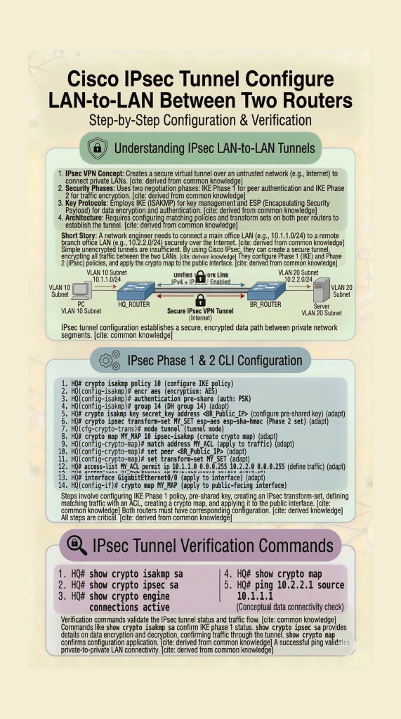
In this lab, you will learn IPsec VPN configuration on Cisco routers using a LAN-to-LAN topology. This step-by-step Packet Tracer lab covers IKE Phase 1, Phase 2, and tunnel verification. This IPsec VPN configuration lab helps you understand how to build secure LAN-to-LAN tunnels in real-world Cisco networks.
Prerequisites
Requirements
There are no specific requirements for this document.
Components Used
The information in this document is based on a Cisco router with Cisco IOS® Release 15.7. It allows users to access resources across the sites over an IPsec VPN tunnel.
The information in this document was created from the devices in a specific lab environment. All of the devices used in this document started with a cleared (default) configuration. If your network is live, ensure that you understand the potential impact of any command.
Conventions
Refer to the Cisco Technical Tips Conventions for more information on document conventions.
Configure
In this section, you are presented with the information to configure the features described in this document. This IPsec VPN configuration lab helps you understand how to build secure LAN-to-LAN tunnels in real-world Cisco networks.
Configurations
This document uses these configurations:
Note: Cisco recommends that the ACL applied to the crypto map on both the devices be a mirror image of each other.
| Router A |
|---|
!--- Create an ISAKMP policy for Phase 1 negotiations for the L2L tunnels. |
| Router B |
|---|
!--- Create an ISAKMP policy for Phase 1 negotiations for the L2L tunnels. |
Verify
Use this section in order to confirm that your configuration works properly.
The Cisco CLI Analyzer (registered customers only) supports certain show commands. Use the Cisco CLI Analyzer to view an analysis of show command output.
show crypto ipsec sa– Shows the settings, number of encaps and decaps, local and remote proxy identities, and Security Parameter Indexes (SPIs), inbound and outbound, used by current Security Associations (SAs).RouterA#show crypto ipsec sa interface: Serial2/0 Crypto map tag: mymap, local addr 172.16.1.1 protected vrf: (none) local ident (addr/mask/prot/port): (10.1.1.0/255.255.255.0/0/0) remote ident (addr/mask/prot/port): (172.16.2.0/255.255.255.0/0/0) current_peer 10.0.0.2 port 500 PERMIT, flags={origin_is_acl,} #pkts encaps: 21, #pkts encrypt: 21, #pkts digest: 21 #pkts decaps: 21, #pkts decrypt: 21, #pkts verify: 21 #pkts compressed: 0, #pkts decompressed: 0 #pkts not compressed: 0, #pkts compr. failed: 0 #pkts not decompressed: 0, #pkts decompress failed: 0 #send errors 0, #recv errors 0 local crypto endpt.: 172.16.1.1, remote crypto endpt.: 10.0.0.2 plaintext mtu 1438, path mtu 1500, ip mtu 1500, ip mtu idb GigabitEthernet0/0 current outbound spi: 0x8767D399(2271728537) PFS (Y/N): N, DH group: none inbound esp sas: spi: 0x6E210372(1847657330) transform: esp-aes esp-sha256-hmac , in use settings ={Tunnel, } conn id: 2007, flow_id: Onboard VPN:7, sibling_flags 80004040, crypto map: mymap sa timing: remaining key lifetime (k/sec): (4338240/3269) IV size: 16 bytes replay detection support: Y Status: ACTIVE(ACTIVE) inbound ah sas: inbound pcp sas: outbound esp sas: spi: 0x8767D399(2271728537) transform: esp-aes esp-sha256-hmac , in use settings ={Tunnel, } conn id: 2008, flow_id: Onboard VPN:8, sibling_flags 80004040, crypto map: mymap sa timing: remaining key lifetime (k/sec): (4338240/3269) IV size: 16 bytes replay detection support: Y Status: ACTIVE(ACTIVE) outbound ah sas: outbound pcp sas:show crypto isakmp sa– Shows all current IKE SAs and the status.RouterA#show crypto isakmp sa dst src state conn-id slot status 10.0.0.2 172.16.1.1 QM_IDLE 1 0 ACTIVEshow crypto map– Shows the crypto map structure created with:- Name of the crypto map and sequence number.
- Peer address.
- Name of the ACL applied along with the local and remote proxy identities.
- Values of the IPsec transform-set used.
- Interface on which the crypto map is binded.
show crypto session remote <IP address of peer VPN endpoint> detailRouterA#show crypto session remote 10.0.0.2 detail Crypto session current status Interface: GigabitEthernet0/0 Uptime: 00:39:16 Session status: UP-ACTIVE >>>>> Status of the VPN Peer: 10.0.0.2 port 500 fvrf: (none) ivrf: (none) Phase1_id: 10.0.0.2 Desc: (none) Session ID: 0 IKEv1 SA: local 172.16.1.1/500 remote 10.0.0.2/500 Active Capabilities:(none) connid:1004 lifetime:23:20:43 IPSEC FLOW: permit ip 10.1.1.0/255.255.255.0 172.16.2.0/255.255.255.0 Active SAs: 2, origin: crypto map Inbound: #pkts dec’ed 21 drop 0 life (KB/Sec) 4338240/1243 Outbound: #pkts enc’ed 21 drop 0 life (KB/Sec) 4338240/1243 RouterB#show crypto session remote 172.16.1.1 detail Crypto session current status Interface: GigabitEthernet0/0 Uptime: 00:40:43 Session status: UP-ACTIVE >>>>> Status of the VPN Peer: 172.16.1.1 port 500 fvrf: (none) ivrf: (none) Phase1_id: 172.16.1.1 Desc: (none) Session ID: 0 IKEv1 SA: local 10.0.0.2/500 remote 172.16.1.1/500 Active Capabilities:(none) connid:1004 lifetime:23:19:16 IPSEC FLOW: permit ip 172.16.2.0/255.255.255.0 10.1.1.0/255.255.255.0 Active SAs: 2, origin: crypto map Inbound: #pkts dec’ed 21 drop 0 life (KB/Sec) 4271304/1156 Outbound: #pkts enc’ed 21 drop 0 life (KB/Sec) 4271304/1156
This IPsec VPN configuration lab helps you understand how to build secure LAN-to-LAN tunnels in real-world Cisco networks.
👉 Related Labs:
– CCNA Lab 1: Configure Hostname and IP Address
– Basic Router Configuration Lab
Nice